The schematic is complete. Done with kicad in a clean manner.
Categories
Schematic first module
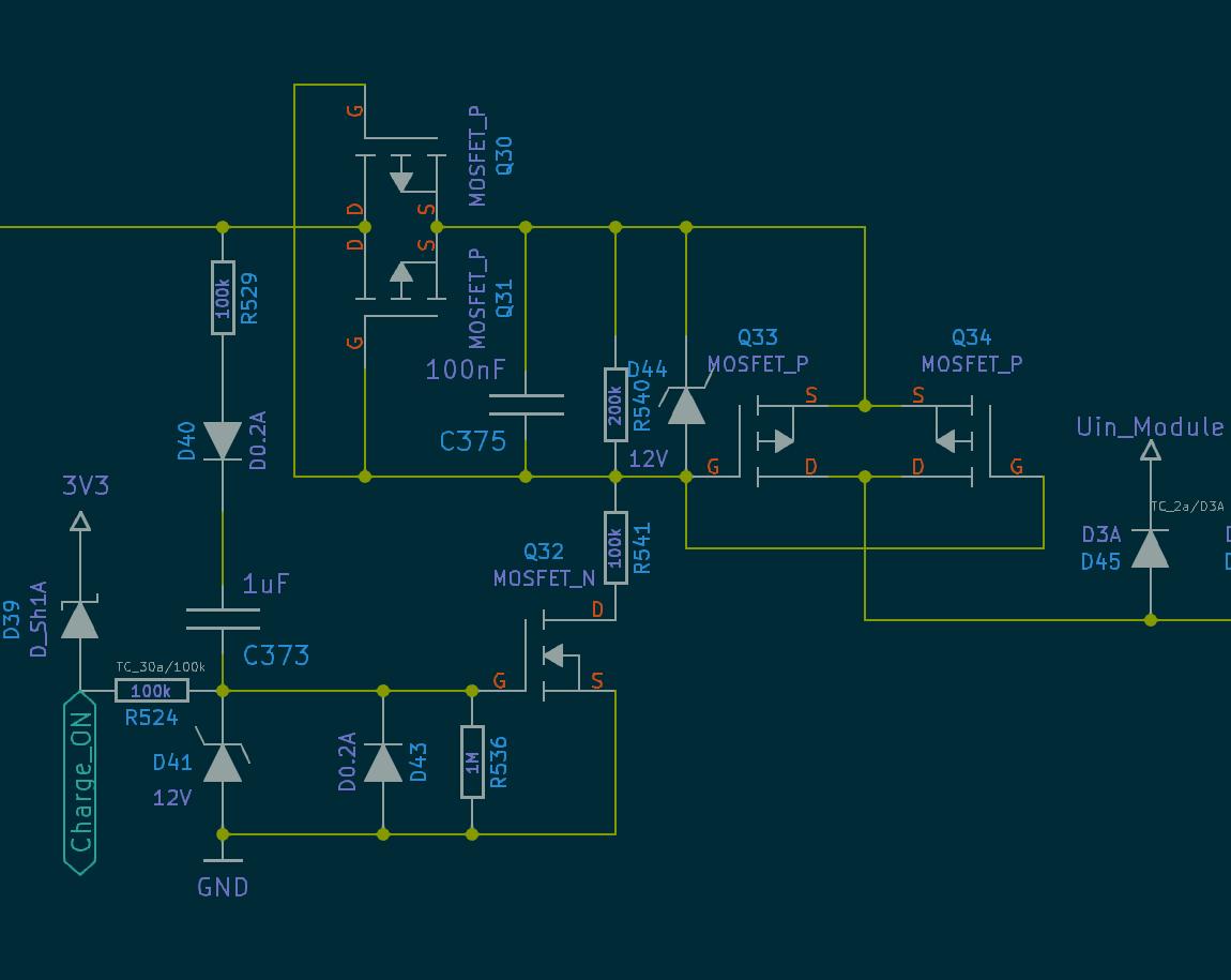
The schematic is complete. Done with kicad in a clean manner.
Before going headlong, a little bit of thinking must be done to avoid some shortcomings in the material design.
Here is an example of this:
What if one day it proves necessary to synchronize the network modules precisely?
No problem, an interruption can be generated when a frame is received on the CAN network. This way, all modules on the network can synchronize their clocks. The tolerance (jitter) would be in the microsecond range. Note also that some microcontrollers make a timestamp at the arrival of a frame. But the timer used for this purpose is based on the clock frequency of the CAN device, which is not necessarily optimal for timing.
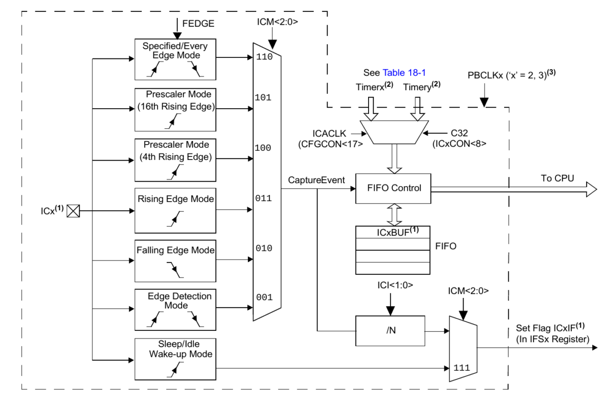
A solution: connect the Rx input of the CAN to the input Capture (IC) peripheral of the microcontroller. This requires no additional components, and the IC is coupled to a timer with a source frequency of up to 100 [Mhz]. Thus, the synchronization of the modules in the network can be done without any problems with a jitter lower than 100 [nS].
The use of an experimental board such as the Curiosity PIC32MZ EF 2.0 Development Board
https://www.microchip.com/DevelopmentTools/ProductDetails/PartNO/DM320209
is an interesting solution to quickly start prototyping.
Basing further development on a highly centralized architecture is a common approach.
The disadvantage is that possible modifications require the entire circuit to be rebuilt.
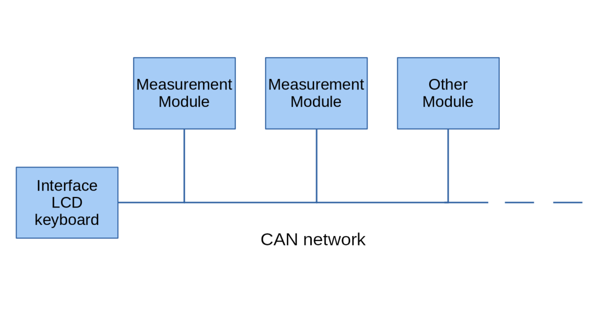
This is why splitting into smaller modules is a more malleable strategy.
The interface (LCD screen, HTML pages) can thus be separated from the measurement modules. This would provide an interface for an entire network of one or more measuring modules.
Smaller modules can then be added to the network as a project develops.
This requires M to M protocol. The CAN protocol is an interesting choice for its ability to connect all the modules in star configuration without having to use a master module that gives the various modules in turn a speaking time. This is because frame collisions are managed physically.
Also, a CAN network does not require all the necessary configurations with Ethernet: no need to configure IPs, etc.
Therefore, we will first focus on the network and the interface before designing measurement modules. This gives the order in which to proceed for the first demonstrator: basic network, an interface, a measurement module.
The idea is to limit the complexity of the first demonstrator. The whole thing can be improved in a second step, especially in terms of software.
Voilà, the association is created, the website configured and the team motivated. The activities of the association officially begin.
It is now time to design the first printed circuit boards. Then, while waiting for the arrival of the components and the assembly, the organization of the firmware can begin.
We will devote a lot of time and effort to all this. In order to finance the prototypes, we will proceed with the background research.
We also hope to write some feature articles on this site.
Also, the documentation will be on the Wiki. We will have to be a little patient: we will advance the project a little bit before putting the documentation online.
As this recent photo shows, an ambitious roadmap has been prepared.